MODEL: GME1024
Specifications:20KW VHF ATV Transmitter Professional used for TV transmitter station
Standard: PAL-D/K/G/I
Frequency: VHF III /VHF-I
Outputpower:≥20kw
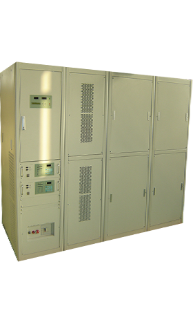
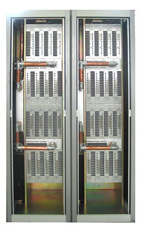
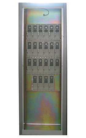
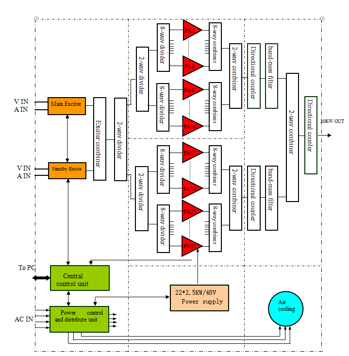
Product introduction:20kw ATV transmitter is made up by eight main parts: exciter, GPS reference clock source, PA, central control unit, power control unit ( contain power distributor), switching mode regulator, passive parts (splitter, combiner, filter, directional coupler, etc.), and cooling system.. Its appearance and internal structure are shown on left.
Click the button below to download the complete technical documentation of this product.
Overview
GME1024 20KW VHF- III/VHF I TV transmitter is made up by eight main parts: exciter, GPS reference clock source, PA, central control unit, power control unit ( contain power distributor), switching mode regulator, passive parts (splitter, combiner, filter, directional coupler, etc.), and cooling system.
Features
1)The transmitter adopts combined amplification of audio and video signals with single transmission link.
2)Redundant backup design minimizes the accident off-air time.
3)Dual exciters configuration – main/standby exciter backups each other. The standby exciter will be switched on automatically with no intermission in case of the main one breaking down accidentally.
4)Redundant PA configuration – The power amplification of 10KW transmitter consists of twenty-four 700W PA modules in high uniformity which makes them able to be replaced with each other freely.
5)Redundant Switching-mode regulator configuration – twelve 3KW switching-mode regulators are connected in parallel with current distribution balanced, the status of which is monitored by the PC. The operation status of the overall transmitter can be regulated automatically according to the status of the switching-mode regulators
6)The transmitter is designed of intelligence and network interface which help to realize monitoring and control and management by means of PC.
7)The transmitter is equipped with comprehensive technical parameter measurement, monitoring and control systems, as well as perfect PC software.
8)The transmitter is equipped with self-diagnosis function.
9)All the technical parameters can be accessed on the LCD on the front panel of the transmitter.
10)With PC interface the main parameters of the transmitter can be set via a PC.
11)Multiple protections minimize the probability of damage of transmitter operating in unfavorable conditions.
12)The transmission system is equipped with protections against video-off, high VSWR, over-temperature, overdrive, phase loss and lightning strikes.
13)The switching-mode regulators system is also protected against over-voltage, over-current, under-voltage, over-temperature, short circuit and lightning strikes.
14)The exciter adopts surface acoustic wave filter, phase locked loop, frequency sythesization, and large scale IC and surface mount technology (SMT).
15)Unique architecture design makes testing, maintenance and transportation easy.
16)Modular Design – either of the different modules is a complete function unit, which makes the transmitter easy to upgrade in a long term perspective.
17)PA and Switching-mode regulator modules are hot pluggable, which makes testing and maintenance convenient and improves the reliability.
18)All the switching-mode regulators are of good quality, high reliability, high efficiency, wide voltage-regulating range and high adaptability.
Cooling mannar adopts exterior placed centrifugal fan to force the air cool.
Operating Channel | VHF-III/VHF I directional channel in frequency band |
Modulation Indepth | ≤87.5% |
Output Power | sync peak power 20KW |
Aural Power 2KW | |
Video Output Power Stability | ±0.25 dB |
Aural/Visual carrier frequency difference | 6.5 MHz±0.166 Hz |
Aural/Visual Power Ratio | 10∶1 |
In-Band Inter-modulation | ≤-51dB |
Non-required emission outside adjacent channel | ≤-60dB |
RF Output Impedance | 50Ω |
RF output connection | Φ79.4 |
Carrier frequency deviation | ±0.051Hz |
Cooling system | Air cooling |
Video Input | 1Vpp±3dB,(75Ω) SECAM D/K |
Reflection Loss of Video Input | ≥30dB |
Amplitude/Frequency response | Refer to table 1 |
Modulation Mode | Amplitude modulation, negative polarity |
Group Delay – Frequency Response | ≤±50ns (0.25MHz-5.8MHz) |
Field Square Wave | ≤2% |
Line Square Wave | ≤2% |
2T pulse | ≤2% |
Luminance Non-linearity Distortion | ≤10% |
Differential gain (DG) | ≤±5% |
Differential phase (DP) | ≤±5° |
Chrominance/Luminance Gain Difference | ±10% |
Chrominance/Luminance Delay Difference | ±30ns |
Signal to Random Noise Ratio S/N (RMS, Un-weighted) | ≥50dB |
Signal to Periodic Noise Ratio S/N (Peak-Peak) | ≥50dB |
Incidental Carrier Phase Modulation(ICPM) | ±5° |
Audio Input | 0dBm±6dBm,600Ω balance |
Modulation mode | FM |
Carrier Frequency Deviation | ±0.051Hz |
Pre-emphasis Time Constant | 50μs |
Maximum Frequency Deviation | ±50KHz |
Audio Harmonics Distortion | ≤1%(30Hz~15KHz) |
Audio Amplitude-Frequency response | ±1dB(Pre-emphasis) |
FM S/N Ratio | ≥60dB |
AM Noise(No modulation) | ≤-50dB |
Inter-carrier Noise (100%modulation ) | ≤-45dB |