10kW FM CDR transmitter
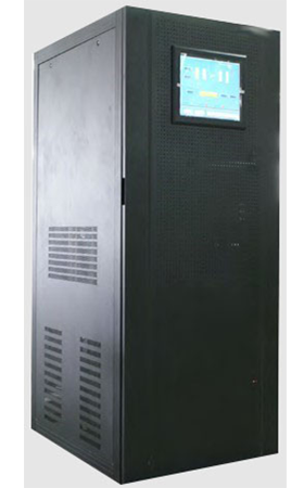
MODEL: GME1R14
Specifications:10KW FM CDR Transmitter Professional used for Digital FM radio transmitter station
Standard: CDR
Frequency: 87MHz~108MHz wideband
Outputpower:≥10kw(In the case of simultaneous broadcasting of digital and analog signals, the output power of the analog signal)
Product introduction:10kw FM CDR transmitter is mainly used for FM frequency band digital audio broadcasting, supporting in band simulcasting of digital audio and analog audio signals. The technical specifications and functions meet the CDR FM frequency band digital audio broadcasting standard, and can achieve three working modes: pure digital signal, pure analog signal, and in band broadcasting of digital and analog signals.
Overview
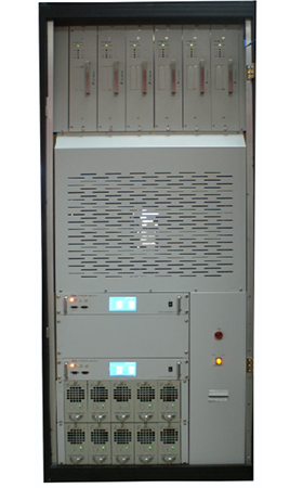
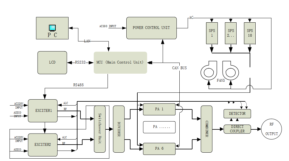
The 10kw CDR FM frequency band digital audio broadcasting transmitter is suitable for three working modes: analog, digital, analog, and digital in band simulcasting. Support all spectrum operating modes required by CDR technology standards. The transmitter mainly includes exciter (modulator), power amplifier, passive components, switching power supply, etc. The output power of the whole machine shall not be less than 10KW (analog output power in the case of simultaneous broadcasting of digital and analog). Digital signal input supports two methods: IP and ASI; Analog signal input supports AES/EBU, XLR, and RDS/SCA signal insertion.
System Characteristics
Advanced technology and design concepts;
LDMOS all solid state technology, the whole machine is fully solid-state;
National patent allocation and synthesis technology;
Modular design concept;
Parallel redundancy design to reduce downtime rate;
Parallel redundancy design of power amplifiers: The transmitter has six identical 2000W power amplifiers, which can be used as backups and can be replaced at will;
Backup redundancy design of power supply: 10 switch power supplies are connected in parallel for current sharing, and the microcomputer monitors the working status of the power supply.
Backup redundancy design of exciter: The main exciter and backup exciter are mutually backed up and automatically switched. (The spare exciter is an optional component.)
Intelligent and networked monitoring system
ARM processor control technology with powerful self diagnostic capabilities.
Touch screen design, simple and practical operation.
Complete data detection technology, monitoring system, and fully functional computer control software.
The CAN bus control system is fast and reliable, making it easy to use computer management and monitoring
Complete protective measures to ensure the safe operation of equipment.
Adopting high-performance high-power amplifier tubes with an anti standing wave ratio of 65:1
The power amplifier is equipped with protections such as VSWR, temperature, and overexcitation.
The switching power supply is equipped with overvoltage, overcurrent, undervoltage, temperature and other protections.
The whole machine is equipped with VSWR, lightning protection, and phase loss protection.
Hot swappable technology, convenient for maintenance and operation
Amplifier hot swappable
Hot swappable switch power supply
No. | Working Mode | Content | Technical Parameter | ||
Digital | Analog+Digital | ||||
1 | * | * | Stepped Frequency | MFN | ≤1kHz |
SFN | ≤1Hz | ||||
2 | * | * | Frequency Stability | Internal clock source | ≤1×10⁻⁷ |
External clock source | ≤1×10⁻⁹ | ||||
3 | * | * | Frequency Accuracy | MFN | ±100Hz |
SFN | ±1Hz | ||||
4 | * | * | Phrase Noise | ≤-60dBc/Hz @10Hz | |
≤-75dBc/Hz @100Hz | |||||
≤-85dBc/Hz @1kHz | |||||
≤-95dBc/Hz @10kHz | |||||
≤-110dBc/Hz @100kHz | |||||
≤-115dBc/Hz @1MHz | |||||
5 | * | * | Load adaptability | Reflection loss≥26dB(Normal work) | |
reflection loss≥20dB(Allow work) | |||||
6 | * |
| Spectrum template | conform to GY/T 268.1-2013 | |
7 | * | * | In band spectrum compliance | ≤1dB | |
8 |
| * | Power uniformity between sub bands | ≤0.5dB | |
9 | * |
| Shoulder | ≤-36dB | |
10 | * | * | Out-of-band spurious | Unused transmission power within adjacent channel bands | ≤-45dB |
Unused transmission power outside the adjacent channel band | ≤-60dB,≤1mW(87MHz below) | ||||
≤-60dB,≤5mW(87MHz~108MHz) | |||||
|
| ≤-60dB,≤1mW(108MHz above) | |||
11 | * | * | RF output power stability | ±0.5dB | |
12 | * |
| peak-to-average power ratio | Conform CCDF | |
Output power | 10KW |
RF output impedance | 50Ω |
Output interface | EIA 1-5/8” non-flange |
Frequency range | 87 -108MHz (when RVR exciter is used, frequency range can only be 87.5-108MHz) |
Frequency stability | +/-1ppm (-10~50°C) |
Sparious radiation | It is less than carrier wave 60dB |
Power voltage | 380V/50Hz, three-phase four-wire |
Power consumption | ≤6KVA(GME1F33)/≤10KVA(GME1F53) |
Boundary dimension | 800(W)*996(D)*1960(H)mm |
Ambient temperature | 5-40℃ |
Altitude | ≤2000m |
Relative humidity | ≤95% |
Remote-control interface | LAN |
Audio input interface | XLR,balanced or imbalanced |
Audio output impedance | 600Ω(balanced)or10KΩ |
Audio input level | -13dBm~+14dBm |
Pre-weighted time constant | 0、50、75us(optional) |
Frequency response | ±0.5dB (30Hz~15KHz) |
Harmonic distortion | ≤0.5%,(30Hz~15KHz) |
FM SNR | ≥70dB |
Separation index of Right and Left Sound Channels | ≥40dB, 100% modulate(30Hz~15KHz) |
Level Difference between Right and Left Channels | ≤0.4dB |
Frequency Deviation of Pilot Signal | ±1Hz |