
CDR Modulator(Exciter)
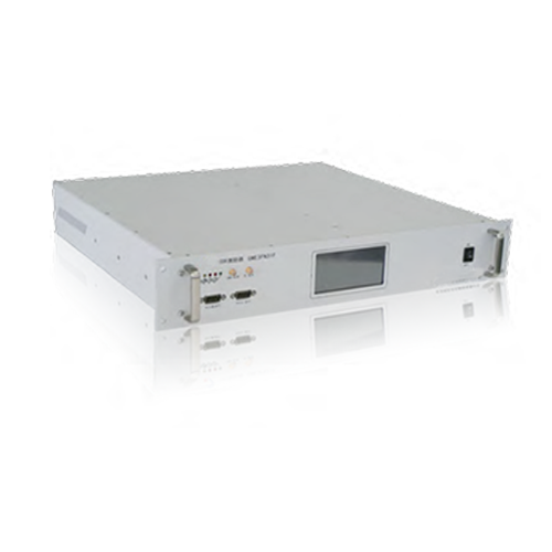
MODEL: DY3FR10
Specifications:CDR Modulator(Exciter) Professional used for digital FM Broadcasting.
Frequency: 87~108MHz
Outputpower:≥30w(Anologue)
Product introduction:The DY3FR10 FM frequency band digital audio broadcasting exciter complies with the GY/T 268.1-2013 “FM frequency band digital audio broadcasting Part 1: Digital broadcasting channel frame structure, channel coding and modulation” (CDR) standard and supports in band simulcasting of FM broadcasting digital and analog signals. This exciter is a new product developed with standardized and serialized appearance and structure, as well as aesthetic effects and practicality. The overall performance is stable and reliable, technologically advanced, easy to operate, and easy to maintain.
Overview
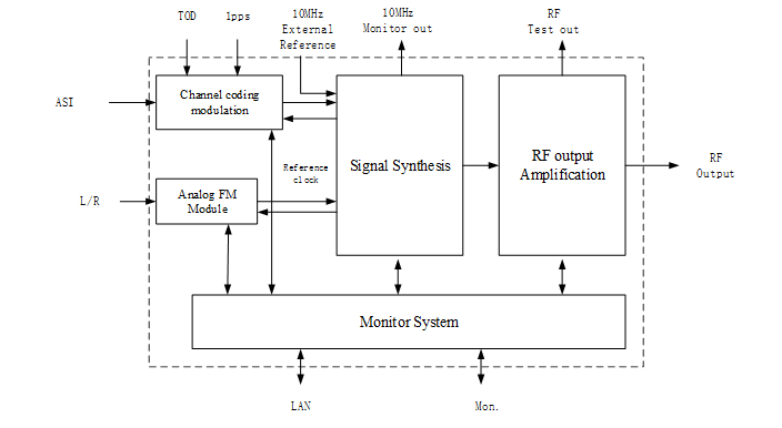
The main circuit of DY3FR10 exciter includes core motherboard (implementing CDR standard coding and modulation, analog frequency modulation, digital analog signal baseband mixing, pre distortion correction, display and control, and external communication algorithm implementation), backplane (external interface circuit and related control interface circuit), frequency conversion board (up conversion TX, down conversion RX, loop and power control), color touch display screen, LED fault display, switch stabilized power supply, fan, and power amplifier modules.
Features
By using a 1000MHz D/A converter, RF output from 87MHz to 108MHz can be directly achieved. The output frequency resolution can reach 32 bits (0.1Hz). Frequency stability<10-8 when working independently;
When using an external GPS10MHz reference source for synchronous operation, the frequency stability is less than 10-9;
It has digital audio signal (AES/EBU), left and right channel analog signal interfaces, and the entire (binary) numerical operation from audio sampling to RF output is at least 24 bit precision and 40 bit accumulator tail number processing;
Equipped with IP and ASI digital audio input interfaces, the input stream complies with DRA (DRA+) standards;
Adopting a color touch screen display, it is clearer and more convenient to operate than an LCD screen.
No. | Working Mode | Content | Technical Parameter | ||
Digital | Analog+Digital | ||||
1 | * | * | Stepped Frequency | MFN | ≤1kHz |
SFN | ≤1Hz | ||||
2 | * | * | Frequency Stability | Internal clock source | ≤1×10⁻⁷ |
External clock source | ≤1×10⁻⁹ | ||||
3 | * | * | Frequency Accuracy | MFN | ±100Hz |
SFN | ±1Hz | ||||
4 | * | * | Phrase Noise | ≤-60dBc/Hz @10Hz | |
≤-75dBc/Hz @100Hz | |||||
≤-85dBc/Hz @1kHz | |||||
≤-95dBc/Hz @10kHz | |||||
≤-110dBc/Hz @100kHz | |||||
≤-115dBc/Hz @1MHz | |||||
5 | * | * | Load adaptability | Reflection loss≥26dB(Normal work) | |
reflection loss≥20dB(Allow work) | |||||
6 | * | Spectrum template | conform to GY/T 268.1-2013 | ||
7 | * | * | In band spectrum compliance | ≤1dB | |
8 | * | Power uniformity between sub bands | ≤0.3dB | ||
9 | * | Shoulder | ≤-40dB | ||
10 | * | * | Out-of-band spurious | Unused transmission power within adjacent channel bands | ≤-50dB |
Unused transmission power outside the adjacent channel band | ≤-60dB,≤1mW(87MHz below) | ||||
≤-60dB,≤5mW(87MHz~108MHz) | |||||
≤-60dB,≤1mW(108MHz above) | |||||
11 | * | * | RF output power stability | ±0.5dB | |
12 | * | peak-to-average power ratio | Conform CCDF | ||