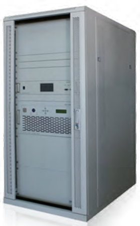
100W/300W FM CDR transmitter
MODEL: GME1R12/GME1R32
Specifications:100W/300W FM CDR Transmitter Professional used for Digital FM radio transmitter station
Standard: CDR
Frequency: 87MHz~108MHz wideband
Outputpower:≥100w or 300w(In the case of simultaneous broadcasting of digital and analog signals, the output power of the analog signal)
Product introduction:100w/300w FM CDR transmitter is mainly used for FM frequency band digital audio broadcasting, supporting in band simulcasting of digital audio and analog audio signals. The technical specifications and functions meet the CDR FM frequency band digital audio broadcasting standard, and can achieve three working modes: pure digital signal, pure analog signal, and in band broadcasting of digital and analog signals.
Overview
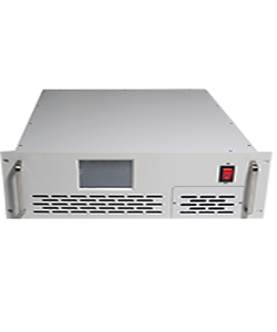
The 100W/300W CDR transmitter mainly includes an exciter and an amplifier unit. The amplifier unit integrates a switch power supply, a control circuit board, an amplifier board, a heat dissipation fan, etc. The transmitter supports in band simulcasting of analog and digital audio signals, and can be set to three working modes: pure digital and pure analog, through the touch frequency setting of the exciter. The transmitter supports all 9 spectrum modes required by the CDR standard, supports digital signal IP, ASI input, supports analog signal AES/EBU and XLR input, and supports RDS/SCA signal insertion.
Technical Feature
1) All solid state technology, the entire machine is designed to be all solid state and broadband within the frequency range.
2) Supports QPSK, 16QAM, and 64QAM; LDPC encoding bit rate: supports four bit rates: 1/4, 1/3, 1/2, and 3/4; Transmission mode: Supports transmission modes 1, 2, and 3.
3) The main components adopt a modular design concept, which is easy to maintain and upgrade.
4) Primary and backup exciters (optional) can achieve dual exciter online redundant protection working mode. In the event of damage or no output from the main exciter equipment, it can quickly and automatically switch to the backup exciter, supporting manual switching between the main and backup exciters.
5) Built in automatic gain, power supply, power control, and multiple protection functions.
6) Micro processing control operations can be achieved through panel and touch screen operations, and touch screen on/off operations require secondary confirmation.
7) The transmitter is equipped with various interfaces such as L&R analog stereo audio, mono input, MPX composite signal input, AES/EBU input, and additional channel SCA/RDS input.
8) The transmitter provides an interlocking protection interface that is compatible with the coaxial switch; The remote control and telemetry function of the transmitter has an IP network interface, remote data communication function, and can be operated remotely for power on and off. The communication protocol is UDP for serial data transmission; The communication interface protocol of the transmitter includes status data of the exciter, amplifier, and switching power supply.
9) Complete protection measures, the transmitter has remote control telemetry and fault alarm functions, and can be integrated into the purchaser’s existing intelligent management system to achieve remote management and monitoring of the transmitter status. We can provide and open up the monitoring and control interface computer protocol of relevant equipment to the purchaser free of charge, and provide software copyright usage rights free of charge.
10) Adopting high-performance high-power amplifier tubes with a standing wave ratio of 65:1.
11) The power amplifier is equipped with protections such as VSWR, temperature, and overexcitation.
12) The switching power supply is equipped with overvoltage, overcurrent, undervoltage, temperature and other protections.
13) The transmitter is equipped with overcurrent, overvoltage, over temperature protection systems and lightning protection measures.
14) Equipped with external power flashing function: The device is not affected by power outages and can save set parameters. After power outages are restored, the configuration parameters before power outages can be called to automatically resume operation.

No. | Working Mode | Content | Technical Parameter | ||
Digital | Analog+Digital | ||||
1 | * | * | Stepped Frequency | MFN | ≤1kHz |
SFN | ≤1Hz | ||||
2 | * | * | Frequency Stability | Internal clock source | ≤1×10⁻⁷ |
External clock source | ≤1×10⁻⁹ | ||||
3 | * | * | Frequency Accuracy | MFN | ±100Hz |
SFN | ±1Hz | ||||
4 | * | * | Phrase Noise | ≤-60dBc/Hz @10Hz | |
≤-75dBc/Hz @100Hz | |||||
≤-85dBc/Hz @1kHz | |||||
≤-95dBc/Hz @10kHz | |||||
≤-110dBc/Hz @100kHz | |||||
≤-115dBc/Hz @1MHz | |||||
5 | * | * | Load adaptability | Reflection loss≥26dB(Normal work) | |
reflection loss≥20dB(Allow work) | |||||
6 | * |
| Spectrum template | conform to GY/T 268.1-2013 | |
7 | * | * | In band spectrum compliance | ≤1dB | |
8 |
| * | Power uniformity between sub bands | ≤0.5dB | |
9 | * |
| Shoulder | ≤-36dB | |
10 | * | * | Out-of-band spurious | Unused transmission power within adjacent channel bands | ≤-45dB |
Unused transmission power outside the adjacent channel band | ≤-60dB,≤1mW(87MHz below) | ||||
≤-60dB,≤5mW(87MHz~108MHz) | |||||
|
| ≤-60dB,≤1mW(108MHz above) | |||
11 | * | * | RF output power stability | ±0.5dB | |
12 | * |
| peak-to-average power ratio | Conform CCDF | |
Audio input interface | XLR,balanced or imbalanced |
Audio output impedance | 600Ω(balanced)or10KΩ |
Audio input level | -13dBm~+14dBm |
Pre-weighted time constant | 0、50、75us(optional) |
Frequency response | ±0.5dB (30Hz~15KHz) |
Harmonic distortion | ≤0.5%,(30Hz~15KHz) |
FM SNR | ≥70dB |
Separation index of Right and Left Sound Channels | ≥40dB, 100% modulate(30Hz~15KHz) |
Level Difference between Right and Left Channels | ≤0.4dB |
Frequency Deviation of Pilot Signal | ±1Hz |